- 您现在的位置:买卖IC网 > Sheet目录17367 > ADM1041-EVAL (Analog Devices Inc)BOARD EVALUATION ADM1041
ADM1041
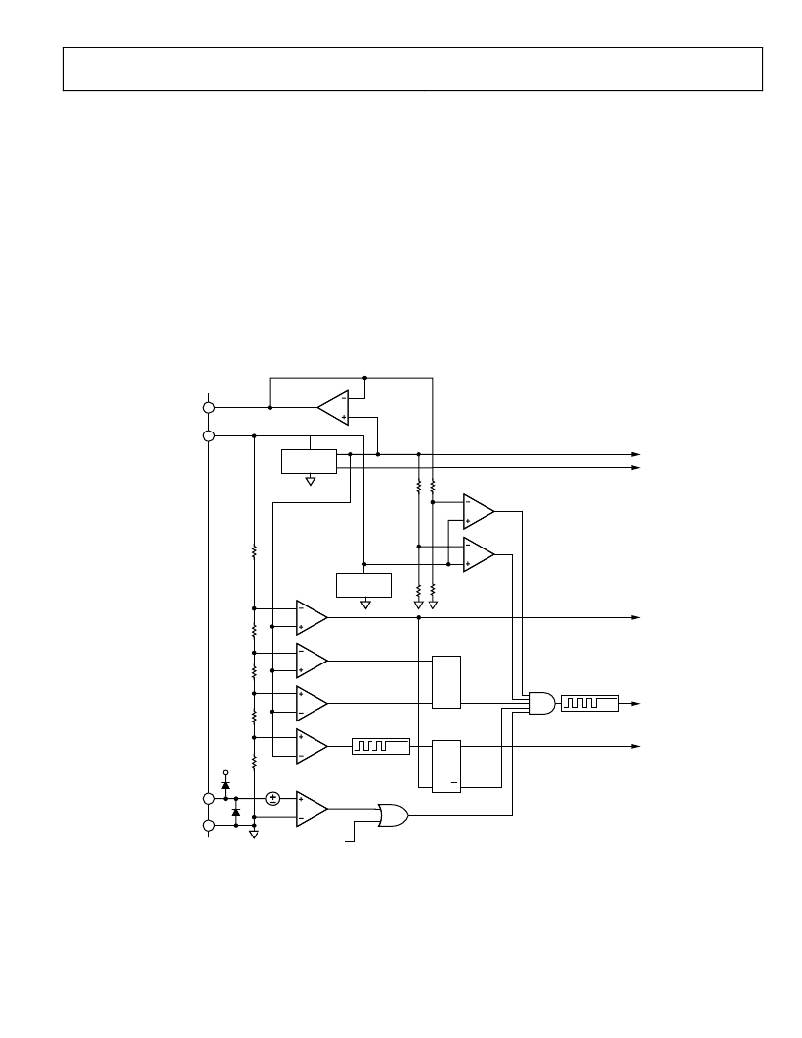
THEORY OF OPERATION
POWER MANAGEMENT
This block contains V DD undervoltage lockout circuitry and a
power-on/reset function. It also provides precision references
for internal use and a buffered reference voltage, V REF . If V REF is
configured to an output pin, overloading, shorting to ground, or
During power-on, V REF does not come up until V DD exceeds the
upper UVL threshold. Housekeeping functions in this block
include reference voltage monitors, V DD overvoltage, and a
ground fault detector.
The ground fault detector monitors ADM1041 ground with
respect to the remote sense pin V S ?. If GND becomes positive
V REF 18
V DD 1
with respect to V S ? an on-chip signal, V DD OK, goes false. V DD OK
is true only when all the following conditions are met: ground is
negative with respect to V S ?, INTREF and EXTREF are operating
normally, V DD > UVLHI, and V DD < V DD OVP threshold.
GAIN TRIMMING AND CONFIGURATION
The various gain settings and configurations throughout the
ADM1041 are digitally set up via the SMBus after it has been
loaded onto its printed circuit board. There is no need for
external trim potentiometers. An initial adjustment process
should be carried out in a test system. Other adjustments such
as current sense and voltage calibration should be carried out in
the completed power supply.
INTERNAL
REFERENCE
2.5V
MAIN
BAND GAP
1.25V
EXTREFOK
REFERENCE
MONITOR
AUXILIARY
REFERENCE
INTREFOK
2.0V
4.0V
POR
UVLLO
S
RESET
4.4V
6.0V–6.5V
UVLHI
OVP
R
S
Q
Q
V DD OK
V DD OV
10 μ s–20 μ s
V S – 20
0.2V
GROUND
MONITOR
GNDOK
R
Q
GND 7
gndok_dis
Figure 8. Block Diagram of Power Management Section
Rev. A | Page 19 of 64
发布紧急采购,3分钟左右您将得到回复。
相关PDF资料
TDC225K025NSE-F
CAP TANT 2.2UF 25V 10% RADIAL
MIC59P50BWM
IC DRVR LATCH 8BIT PAR IN 24SOIC
A9AAT-0906F
FLEX CABLE - AFE09T/AF09/AFE09T
ISL85033EVAL2Z
EVAL BOARD2 FOR ISL85033
MIC5891BWM
IC DRVR LATCH 8BIT SER IN 16SOIC
MIC5891BN
IC DRVR LATCH 8BIT SER IN 16DIP
TAAB336K010G
CAP TANT 33UF 10V 10% AXIAL
SPX385AS-L-1-2
IC VREF SHUNT PREC 1.235V 8SOICN
相关代理商/技术参数
ADM10470J
制造商: 功能描述: 制造商:undefined 功能描述:
ADM1051
制造商:AD 制造商全称:Analog Devices 功能描述:Precision Dual Voltage Regulator Controllers
ADM1051A
制造商:AD 制造商全称:Analog Devices 功能描述:Precision Dual Voltage Regulator Controllers
ADM1051AJR
制造商:Analog Devices 功能描述:DC DC Cntrlr Dual-OUT Step Down 12V Input 8-Pin SOIC N 制造商:Analog Devices 功能描述:DC DC CNTRLR DUAL-OUT STEP DOWN 12V 8SOIC - Bulk 制造商:Rochester Electronics LLC 功能描述:ENHANCED DUAL BUS TERMINATOR - Bulk
ADM1051AJR-REEL
制造商:Analog Devices 功能描述:DC DC Cntrlr Dual-OUT Step Down 12V Input 8-Pin SOIC N T/R 制造商:Analog Devices 功能描述:DC DC CNTRLR DUAL-OUT STEP DOWN 12V 8SOIC N - Tape and Reel 制造商:Rochester Electronics LLC 功能描述:ENHANCED DUAL BUS TERMINATOR - Tape and Reel
ADM1051AJR-REEL7
制造商:Analog Devices 功能描述:DC DC Cntrlr Dual-OUT Step Down 12V Input 8-Pin SOIC N T/R 制造商:Analog Devices 功能描述:DC DC CNTRLR DUAL-OUT STEP DOWN 12V 8SOIC N - Tape and Reel 制造商:Rochester Electronics LLC 功能描述:ENHANCED DUAL BUS TERMINATOR - Tape and Reel
ADM1051AJRZ
制造商:Analog Devices 功能描述:DC DC CNTRLR DUAL-OUT STEP DOWN 12V 8SOIC N - Bulk
ADM1051AJRZ-REEL
制造商:Analog Devices 功能描述:DC DC CNTRLR DUAL-OUT STEP DOWN 12V 8SOIC N - Tape and Reel
